This is the third of five articles in the series “Reactive Power in Utility-Scale Solar PV Applications.”
Inverters are a key component of any IBR (Inverter-Based Resources) facility, including Utility-Scale Solar PV. Because of their ability to control different output quantities, including real power, reactive power, disturbance ride-through, and ramp rates, inverters are sometimes called the “brains” of the renewable energy or storage facility.
Inverters are rated in terms of apparent power kVA. They may also have a real, or active, power rating in kW that is equal to or less than the kVA rating. It’s important to distinguish whether a numerical rating refers to kW or kVA, as we shall see in a later article.
Power Triangles and the Apparent Power Circle
To understand reactive power capabilities of inverters, it helps to know that real (active) power (kW), reactive power (kVAR), and apparent power (kVA) are all related mathematically by the equation kW2 + kVAr2 = kVA2 (Thank you Pythagoras – for a right triangle, the sum of the squares of the two sides equals the square of the hypotenuse).
As painful as it is, if you recall additional memories of high school geometry, you might remember that the equation for a circle centered at the (0,0) coordinates is x2 + y2 = r2, where “r” is the circle’s radius. This is exactly the same as the power equation above.
So, the power equation, kW2 + kVAr2 = kVA2 is not only a right triangle when you insert appropriate values into the variables, but it’s also a circle if you consider all combinations of the values of kW2 and kVAr2 that result in a single value of kVA2. Mind-blowing, right?
You’re thinking, “Tim – thanks for the theory. I’ll tell that to my kids or my friends at the next barbeque and show them how cool I am.” Which is exactly what I do. But hold on, let’s look at a picture – it’s worth, what, at least 9 or 10 words?
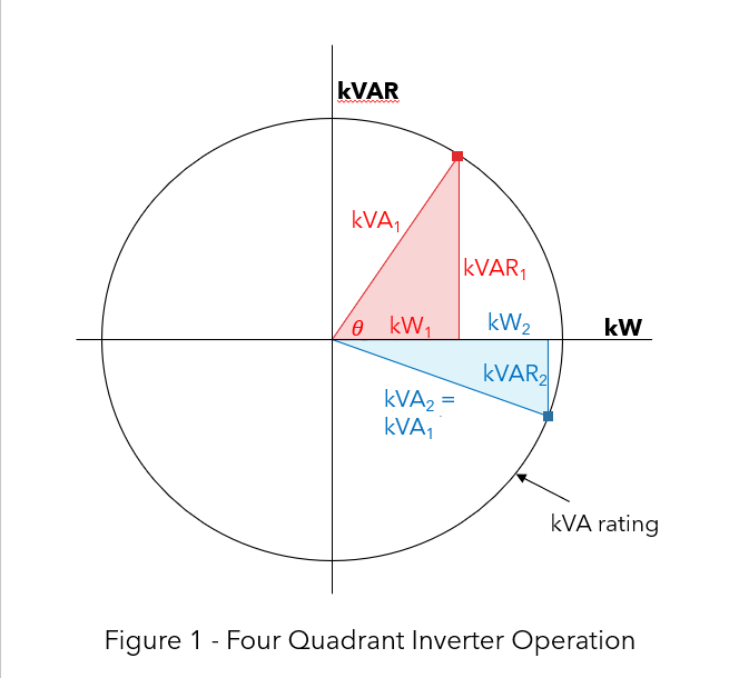
The upper half of the circle represents reactive power injection into the system (positive kVAR, like a shunt capacitor), while the lower half represents reactive power absorption from the system (negative kVAr, like a shunt inductor.)
Operation at kVA rating are the points on the circle. A generator inverter can operate anywhere within the right half of the circle, which is when the inverter is not operating at its kVA rating. (However, as we shall see later, many inverters are designed to limit the number of kVAr supplied at a specific power factor.)
The red triangle in Figure 1 is drawn to show that if the inverter is operating at kW1 and kVAr1, then the inverter is operating at the red square on the kVA rating circle. The blue triangle in Figure 1 is drawn to show that if the inverter is operating at kW2 and kVAr2, then the inverter is operating at the blue square on the kVA rating circle. For both points, kVA1 = kVA2 = kVArating.
And the extra credit question: What does operation at all the points along either one of the hypotenuses represent?
Answer: It represents constant power factor operation. The key to understanding that is the angle θ (theta) depicted in the red triangle. The cosine of θ is equal to the power factor. θ stays constant as you move up and down the red kVA1 hypotenuse. Since θ stays constant, the cosine of θ stays constant, and the power factor stays constant. Geometry is beautiful, hey?
Inverter Reactive Power Capabilities
Because of the benefits that IBR with VAr injection or VAr absorption can provide to the grid, technical standards and grid codes are now specifying the reactive power capabilities of grid-connected DER (Distributed Energy Resources), including Solar PV, batteries, and modern wind turbines.
IEEE 1547-2018TM specifies reactive power capabilities that all distribution-connected DER must have, including IBR like solar PV. Keep in mind that not all US states have adopted the IEEE 1547-2018 standard as of 2023.
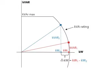
Figure 2 shows that for all real power generation above 0.2 x Prated, the DER must be capable of supplying or absorbing reactive power of at least 0.44 x Srated, with S the apparent power rating of the DER (e.g., in kVA). At the two points defined by Prated and 0.44 x Srated, the operating points lie on the circle and have a power factor of 0.9. The DER must be able of supplying or absorbing reactive power, as specified in the figure, down to 0.05 x Prated.
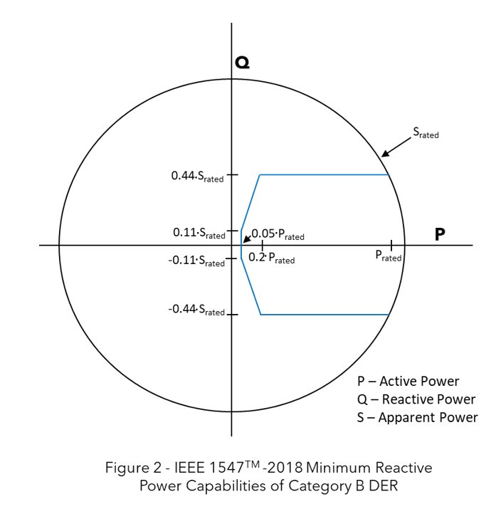
Keep in mind that Figure 2 represents minimum reactive power capabilities, and it is applicable to DERs and not inverters themselves. But some inverters surpass the minimum requirements in Figure 2. As shown in Figure 3, some inverters have Srated capability to +/- 0.8 pf, compared to the +/- 0.9 pf point in Figure 2. (Note Figure 3 does not show the entire Srated circle – it only shows the actual inverter capability in the real power-producing quadrants.)
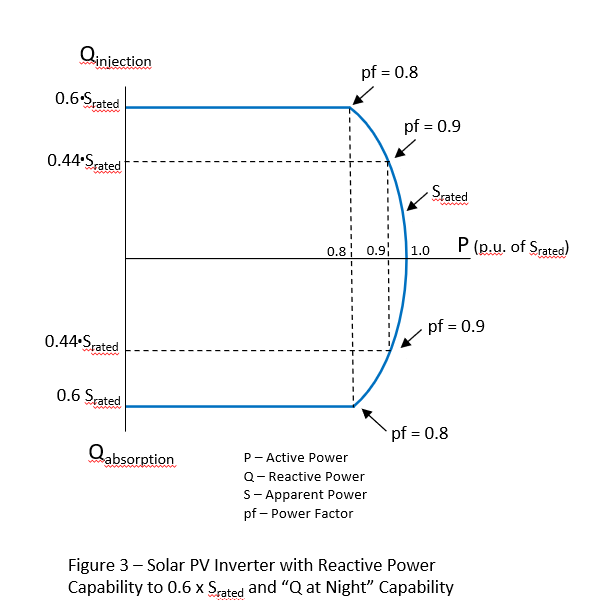
The reactive power can be as high as 60% of rated active power at night. Special rectifier hardware is added to the inverter, and the inverter must be kept connected to the grid at night. There must be incentives for developers and owners for Q at Night to be viable.
In the next article in this series Reactive Power in Utility-Scale Solar PV Applications, we’ll build on these concepts and look at “Active Power Priority vs. Reactive Power Priority.”
Tim Taylor is the founder of Electric Distribution Academy, and all his courses are hosted exclusively on HeatSpring. Tim is the instructor for several courses focused on utility distribution, including “Interconnection of Utility-Scale Solar PV to Distribution” and “Understanding IEEE 1547-2018 – Interconnection Standard for DER on Distribution.