This is the first of five articles in the series “Reactive Power in Utility-Scale Solar PV Applications.”
Right after I started my first job out of college, I found myself presenting at a meeting and talking about reactive power and VArs. These were very senior-level engineers, and, although I didn’t recognize it at the time, never short on humor. One guy starts going on about how he’s not understanding what I’m talking about. So I try another way. And he says he still doesn’t get the concept of reactive power or these VArs. Finally, he says, “Tim, you keep mentioning these VArs. It may help if you’re more specific – are you talking about grizzly VArs or polar VArs?” Ha ha ha. I’d been had. But I wouldn’t have traded my experience with those guys for anything.
Before we get to Reactive Power, let’s talk about Real Power and Apparent Power.
Real Power
Real power, also referred to as active power (measured in Watts, such as kW – kiloWatt), wins the “Most Popular in Class” title over 1) reactive power, also referred to as “imaginary” power (measured in Volt-Amperes reactive, such as kVAr – kiloVolt-Amperes reactive), and 2) apparent power (commonly measured in VA, such as kVA – kiloVolt Amperes). After all, it’s the real power supplying kW over time and producing real energy (kWh) where renewable plants earn all or at least most their money.
The end-product of real power is usually observable, and it does real work – it gives us light, it spins motors, it provides heat from space heaters, it lets us watch “Ted Lasso”. With real power the ac voltage is in phase with the ac current, which occurs when you apply an ac voltage across a resistor.
Apparent Power
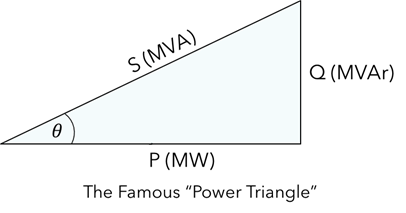
They are related by the equation MW2 + MVAr2 = MVA2, using “M” to mean 1,000,000 (although you could “k” or any other multiplier). The “Power Triangle” relates all three, with the angle theta being the angle between the voltage and current waveforms. Cosine theta, or P/S is the power factor, which must be between 0 and 1.
Reactive Power
With reactive or imaginary power, it can be difficult to visualize how an ac current creates a magnetic field in and around a coil of wire, or how an ac voltage creates an electric field across two plates. But even though it’s difficult to see, unlike real power, make no mistake – reactive power is instrumental in how ac power systems function electrically (and magnetically).
As we said earlier, with real power the ac voltage is in phase with the ac current. But with reactive power, the ac voltage is 90o out of phase with the current. This results from the application of equipment that has inductive or capacitive properties.
Inductive Loads
Equipment with high “inductive” reactance include transformers, motors, reactors, and even transmission/distribution lines.
In such equipment, an electromagnetic field is established, with the result that the reactive portion of the current lags the ac voltage by 90o.

Capacitive Loads
Capacitors and loads with capacitive components are a bit different because the physical phenomenon is the electric field. Capacitors create current that lead the voltage by 90o, which is completely opposite of inductors. The result is that shunt capacitors generate VArs and can be used to “compensate” for all the VArs that components like transformers and motors absorb.
Absorbing and Generating VArs
A simple convention to use is that inductive loads and components “absorb”, or consume, Vars. Capacitive loads, such as shunt capacitors, “supply” VArs.
In ac power systems, it’s typical that loads and equipment with inductive components are much greater than the capacitive loads and equipment components. The result is that the loads typically absorb VArs.
Also, typically it is equipment like large generators and shunt capacitors that generate the VArs required for the inductive loads and equipment. However, generators, including both rotating synchronous generators and inverter-based generators like renewables, can also absorb VArs.
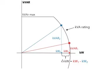
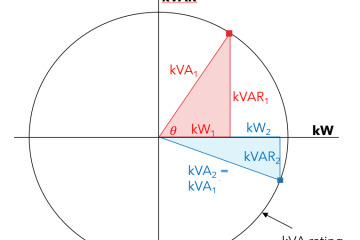
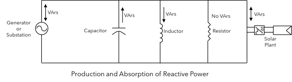
The figure below is a simple generalization that typically generators can either absorb or produce VArs, shunt capacitors will produce VArs, and inductors absorb VArs. Components and loads on power system are usually a mix of capacitive, inductive, and resistive properties. As a result, the power factor is rarely exactly 0 or 1, but some value in-between. Usually it’s between 0.9 and 1.0.
In the next article in this series Reactive Power in Utility-Scale Solar PV Applications, we’ll look at “Reactive Power and Transmission & Distribution Operations.”
Tim Taylor is the founder of Electric Distribution Academy, and all his courses are hosted exclusively on HeatSpring. Tim is the instructor for several courses focused on utility distribution, including “Interconnection of Utility-Scale Solar PV to Distribution” and “Understanding IEEE 1547-2018 – Interconnection Standard for DER on Distribution.